A couple of years ago someone brought to me a Cobra 25LTD Chrome that was dead, it had a failure of the YD1022 audio chip. Which, if you've ever looked for it, you'll know that it is unobtanium.

Since it was in such good nick, and I can't entertain the idea of throwing a radio away I thought I'd see if it could be revived. What audio amps did I have in my spares drawers? Not a huge selection, a few high powered ICs that needed dual power supplies and an LM386M-82. That can deliver maybe a watt? It should be enough for shack use? If you are going to buy an LM386, choose the highest output power model you can get.
1) Unsolder the speaker wires. Desolder and remove the duff YD1022 if you haven't already. Throw it in the bin with anger and hatred. Put some solder back on the audio IC pads. Clean up the board with IPA and cotton bud. Note the order of the pins, on my board it is stamped 1 and 10 on each side. If yours isn't marked, with the knobs on the right and the underside of the pcb facing you, pin 1 is on the right hand side.
2) Pins 9 and 10 on the PCB is the +V supply to the ex-audio IC. Note the PCB track. Pins 7 and 8 on the PCB is the audio output. Note the PCB track. Pins 5 and 6 are GND. Pin 3 is the inverting input. Pin 2 is the non-inverting input.

3) Take the LM386, and bend out straight pins 1, 2, 3, 5, 7, 8

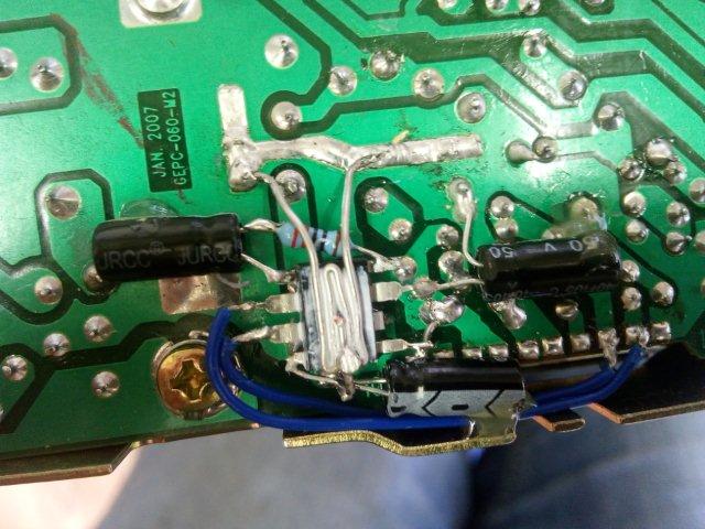
4) Pin 4 on the LM386 needs to go to ground. Pin 6 needs to connect to +V. Trim the pins 4 and 6, leaving about 1mm of the thin part of the leg left. There is a ground PCB track a little further left from the +V track. You can see a little red - in the above photo. Use positions on these tracks to connect to pins 4 and 6, you should be able to find points that leave the IC nice and straight on the board. Solder the IC in place.
5) Solder pin 5 of the LM386 down to the track connected to Pins 7 and 8 on the PCB. I used a small piece of single core wire to help reach.
6) Solder a 100uF capacitor from +V track to pin 4 on the LM386. Capacitor - towards pin 4. This capacitor is required for stability. It is the capacitor in the lowest position in the photo.
7) Solder a 1uF capacitor from ground to pin 7 on the LM386. Capacitor - towards ground. This capacitor is required for stability. This is the capacitor on the right hand side in the photo.
8) Snip off the thin part of the leg on pin 1 of the LM386. Solder the + leg of a 1uF capacitor to pin 1. Snip off the thin part of the leg on pin 8. Solder a 220 ohm resistor to pin 8 and solder the other side to the - of the capacitor. Push the resistor down a bit so it's below the level of the top of the LM386. The capacitor and resistor set the gain of the LM386.

9) Fold a piece of single core wire into a zig zag with some long nose pliers to make a heatsink for the IC, as shown in the picture. Trim it to fit, put a small dab of heatsink compound on the top of the IC and solder the wire to the ground points a cm or so north of the IC. Solder a small piece of wire to the - of the 100uF capacitor connected to pin 4, to the zigzag, to hold it tight onto the IC. Snip close to the solder joint as possible. Use a file to take the top off the solder joint if it's sticking up too much.
10) Solder pin 2 on the PCB to pin 2 on the LM386. Solder pin 3 on the PCB to pin 3 on the LM386. These are the blue wires on the photo.
11) Add a little contact adhesive or hot glue on to the ends of the capacitors, to provide a bit more mechanical fixing for them.
12) Solder the speaker back on. Test. Don't forget to plug the mic in. Otherwise no sound!
For me, there is easily enough audio power for shack use, and enough for the car when stopped. There is also plenty of modulation. The 220 ohm resistor controls the gain of the LM386. Go lower to go louder, though 220 ohm seems just right.