Repairs
My AT5555 has been dormant for quite a few years and I had the urge to try it out and test it, after giving the Cobra 29LTD AM rig a whirl. SSB receive quality was terrible, really really bad. Then I noticed that it was receiving on adjacent channels! This usually means transmitting on adjacent channels too :O
So I had a poke around with the scope and spectrum analyser to see what was wrong. I figured that something somewhere must have gone distorted and checked out the BFO circuit... urgh! It was like this:
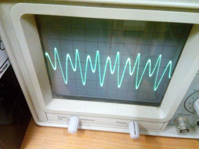
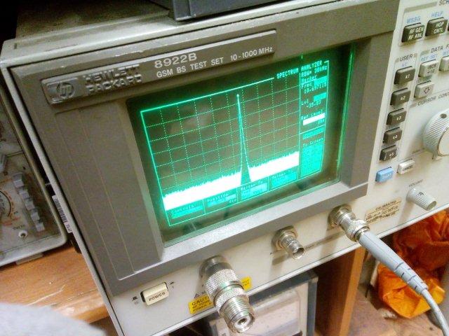
When it should have been like this:
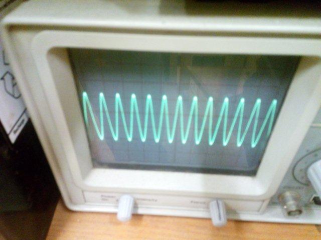
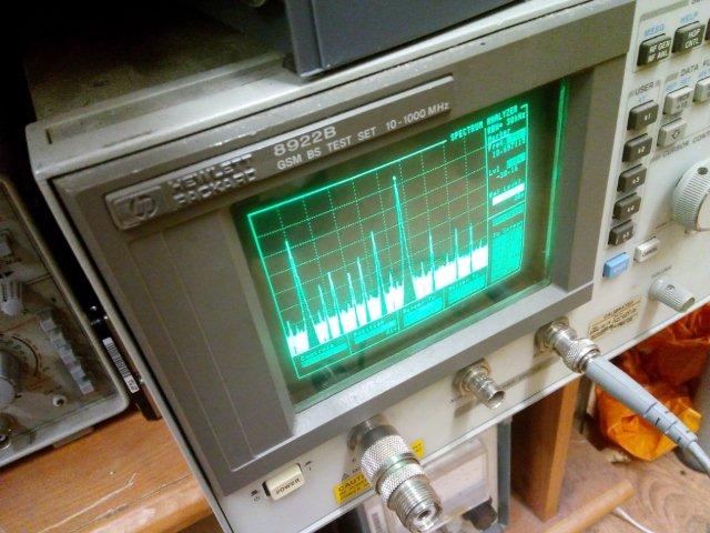
Analyser showing 5-15Mhz. I had been using this for a QSO! I dread to think where it was transmitting! When I bought the radio, I found that the BFO was slightly unstable, after the radio warmed up it would make a little step change in frequency. It was minor, but enough to be annoying. I changed a resistor R68 from a 56k to a 68k, which you can see standing up in the photo and which cured the problem at that time. But in the long time that it had been switched off, something has changed slightly and the BFO circuit is not functioning properly again.
So, I removed the 68k and replaced it with a 47k. This seemed to solve the wonky oscillator problem (but now occasionally on power up the oscillator fails to start!) But the fine tune was all wonky too, and generally the rig was misaligned, especially on CW, receiving 1Khz off and several hundred Hz off for USB and LSB. Tuning up and down with the clarifier was not continuous, it stepped incorrectly every 100Hz and was just plain wrong.
First reset the AT-5555 by holding down FUNC and SCAN while turning the radio on. On my radio, this defaults to the frequency range 25.615 to 28.305Mhz.
There is a service menu - Turn on holding FUNC, then press RB, then NB, then DW. There is no documentation for these settings so I have worked out what each of them are.
For each MODE switch position, there are alignment settings. Some are shared. You can scroll through them by pressing FUNC. The settings are bfC, fr0, fr4, fr5, fr9, loC.
bf adjusts the frequency of the 10.24Mhz BFO
fd0,4,5,9. What do these control? Hmmm. Bingo! These are for fine tuning! The radio performs fine tuning by adjusting the voltage across a set of varicaps, which affects capacitance and hence the frequency of the oscillator. These must be the limit voltages for .00, .04, .05, .09
lo controls the local oscillator offset.
**WRITE DOWN THE ORIGINAL SETTINGS FOR EACH MODE before performing the alignment**
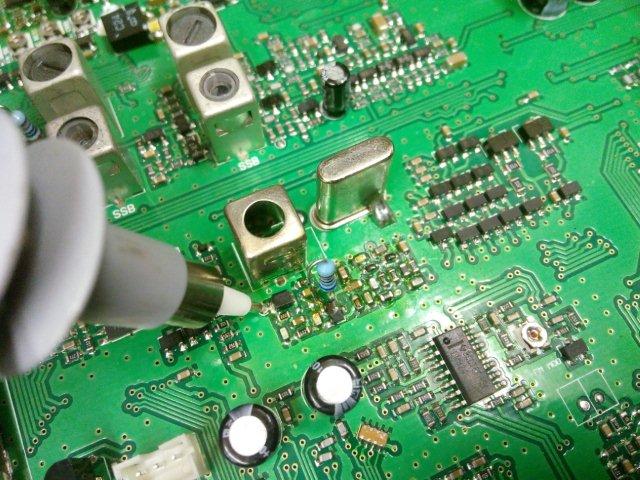
Connect a frequency counter to the BFO test point. It is shown in the above picture with the probe on it.
Enter alignment mode. For each mode, set bf so the frequency is as specified
CW 10.6950MHz
FM 10.6950MHz.
USB 10.6925MHz.
LSB 10.6975MHz
Connect a signal generator at S9, -73dBm, 50uV, 27.860Mhz
Set lo for a tone of 800Hz. (mine was -5000Hz) for CW
Set lo to center RX, check the offset in normal mode (-5000Hz) for FM
Set lo to zero beat (0Hz) the tone (-1700Hz) for USB
Set lo to zero beat (0Hz) the tone (-5000Hz) for LSB
[The offsets seem fairly skewed in my radio, this could indicate a problem, a comparison here with a known good radio would be useful]
Connect frequency counter to audio output
Set to CW, maintain sig gen at 28.860Mhz.
Set fr0 for 800Hz
Set fr4 for 760Hz
Set fr5 for 750Hz
Set fr9 for 710Hz
Set to USB, change sig gen to 28.861Mhz
Set fr0 for 1000Hz
Set fr4 for 960Hz
Set fr5 for 950Hz
Set fr9 for 910Hz
Set to LSB, change sig gen to 28.859Mhz
Set fr0 for 1000Hz
Set fr4 for 1040Hz
Set fr5 for 1050Hz
Set fr9 for 1090Hz
Since the sig-gen is connected, turn RF gain all the way up, check level is at 50uV or -73dBm, tune to the signal and set SSB RSSI pot for S9 on the meter in SSB mode and FM RSSI pot for S9 in FM mode.
I found at the end of this I was still slightly off on USB and LSB. If this is the case change lo *first* to get as close as possible, then tweak bf for the final step. This reduces the amount bf needs to change, preserving your fr settings.
Go back to normal mode and check each mode for correct operation. Check the fine tuning is even and smooth. If not, repeat the fr0-9 steps for that mode. You can try one click for bf if the radio is very slightly off frequency on CW, USB or LSB. Any significant change of bf requires fr0-9 alignment.
Feedback and double checking welcome on this procedure.
- Details
- Written by Super User
- Category: Repairs
- Hits: 39580
A couple of years ago someone brought to me a Cobra 25LTD Chrome that was dead, it had a failure of the YD1022 audio chip. Which, if you've ever looked for it, you'll know that it is unobtanium.

Since it was in such good nick, and I can't entertain the idea of throwing a radio away I thought I'd see if it could be revived. What audio amps did I have in my spares drawers? Not a huge selection, a few high powered ICs that needed dual power supplies and an LM386M-82. That can deliver maybe a watt? It should be enough for shack use? If you are going to buy an LM386, choose the highest output power model you can get.
1) Unsolder the speaker wires. Desolder and remove the duff YD1022 if you haven't already. Throw it in the bin with anger and hatred. Put some solder back on the audio IC pads. Clean up the board with IPA and cotton bud. Note the order of the pins, on my board it is stamped 1 and 10 on each side. If yours isn't marked, with the knobs on the right and the underside of the pcb facing you, pin 1 is on the right hand side.
2) Pins 9 and 10 on the PCB is the +V supply to the ex-audio IC. Note the PCB track. Pins 7 and 8 on the PCB is the audio output. Note the PCB track. Pins 5 and 6 are GND. Pin 3 is the inverting input. Pin 2 is the non-inverting input.

3) Take the LM386, and bend out straight pins 1, 2, 3, 5, 7, 8

4) Pin 4 on the LM386 needs to go to ground. Pin 6 needs to connect to +V. Trim the pins 4 and 6, leaving about 1mm of the thin part of the leg left. There is a ground PCB track a little further left from the +V track. You can see a little red - in the above photo. Use positions on these tracks to connect to pins 4 and 6, you should be able to find points that leave the IC nice and straight on the board. Solder the IC in place.
5) Solder pin 5 of the LM386 down to the track connected to Pins 7 and 8 on the PCB. I used a small piece of single core wire to help reach.
6) Solder a 100uF capacitor from +V track to pin 4 on the LM386. Capacitor - towards pin 4. This capacitor is required for stability. It is the capacitor in the lowest position in the photo.
7) Solder a 1uF capacitor from ground to pin 7 on the LM386. Capacitor - towards ground. This capacitor is required for stability. This is the capacitor on the right hand side in the photo.
8) Snip off the thin part of the leg on pin 1 of the LM386. Solder the + leg of a 1uF capacitor to pin 1. Snip off the thin part of the leg on pin 8. Solder a 220 ohm resistor to pin 8 and solder the other side to the - of the capacitor. Push the resistor down a bit so it's below the level of the top of the LM386. The capacitor and resistor set the gain of the LM386.

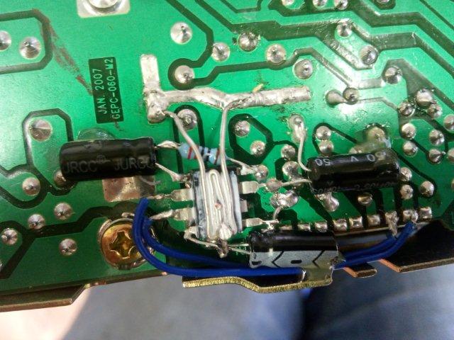
9) Fold a piece of single core wire into a zig zag with some long nose pliers to make a heatsink for the IC, as shown in the picture. Trim it to fit, put a small dab of heatsink compound on the top of the IC and solder the wire to the ground points a cm or so north of the IC. Solder a small piece of wire to the - of the 100uF capacitor connected to pin 4, to the zigzag, to hold it tight onto the IC. Snip close to the solder joint as possible. Use a file to take the top off the solder joint if it's sticking up too much.
10) Solder pin 2 on the PCB to pin 2 on the LM386. Solder pin 3 on the PCB to pin 3 on the LM386. These are the blue wires on the photo.
11) Add a little contact adhesive or hot glue on to the ends of the capacitors, to provide a bit more mechanical fixing for them.
12) Solder the speaker back on. Test. Don't forget to plug the mic in. Otherwise no sound!
For me, there is easily enough audio power for shack use, and enough for the car when stopped. There is also plenty of modulation. The 220 ohm resistor controls the gain of the LM386. Go lower to go louder, though 220 ohm seems just right.
- Details
- Written by Super User
- Category: Repairs
- Hits: 21996
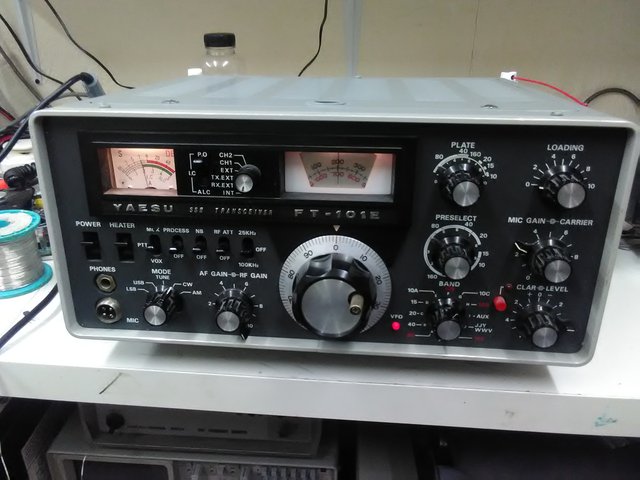
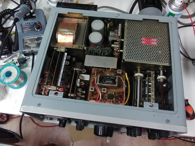
Radio with severe problems. This 'lovely' radio has haunted me for years!
1. Dead TX
R5 5.1k 3W in the driver valve compartment was cooked and open. Replaced. So was an electrolytic capacitor in there, underneath the long power resistor.. Replaced.
2. Very low power on 20m
20M plate trimmer bad and capacitor underneath it too. Replaced.
3. Misalignment
When following the alignment instructions for the preselector tuning coils, T101A would always end up 5mm up because the peak could not be found. The instructions say put the 10m trimmer TC15 to mid-capacitance position. I had to go for 1/3 capacitance position, then T101A would peak. The tuning slugs in the three inductor cans should not be in wildly different positions, mine are within 1mm of each other. Initial settings I found to be good for the slug position, when attempting realignment of the preselector coils from scratch were for the slug tops to be level with the white sleeve top at a preselector setting of 2 on the inner scale. I have read elsewhere that 4.1 is correct, but that would not allow me to tune preselect on the bottom edge of the band for 160m. At 2, it just fades off at 1.8Mhz and still allows tuning of the top end of 10m. So if the alignments are lost, preset the slugs to 2.
The S meter should be set to S9 for 50uV. The crystal calibrator is 50uV, so use that at 14.2Mhz to align the S meter. The service manual says to set it to S9+25dB, but this is too high in my opinion, especially for 80m.
G3YRO's trimmers alignment procedure (thank you!):
The most important thing to remember on these rigs is that you shouldn't transmit full power carrier for more than a couple of seconds at a time, if you want the PA Valves to last. (do that and they will last 30+ years)
So when carrying out alignment on Transmit, always monitor the PA Current (Ic), and keep re-adjustinging the Carrier control to keep the current below 150mA. Also do each Transmit peak in short 2-3 second bursts.
Stand the rig upright on its left hand side (on its feet), and remove the bottom plate. (no need to remove the Tx screening panel unnderneath).
Connect a Dummy Load
Leave the Mode switch in the Tune position.
Meter in the PA Current (Ic) position)
PA Load control at 0.
PA Tune control in the middle of the marked position for that band.
To gain access to SOME of the trimmers, you may need to just remove a couple of the case screws and pry up the case that overlaps the bottom, near the front of the rig. (with a flat screwdriver)
1. Starting on 80m, go to the middle of the band. Peak the Pre-selector on the Calibrator signal, and then leave it there.
2. Peak the Band Crystal trimmer for that band for max S Meter reading. Then go to Transmit (keeping the PA Current below 150mA) and peak that Crystal trimmer for max PA current.(this is because you can get a more accurate peak on Transmit)
3. On Receive, peak the RF Stage and Mixer Trimmers for maximum S Meter reading.
4. Go to Transmit, peak the Grid Tuning trimmer for maximum PA current. Then adjust the PA Tune control for a Dip (minimum PA Current). Then re-peak the Grid trimmer (it may have changed slightly).
5.Go to Transmit, peak the Mixer Trimmer for maximum PA Current.
6. Repeat all of the above for 40m, 20m, 15m and 160m bands.
7. Go to 10m, and peak EACH of the 4 band segment crystals on Receive, then Transmit. (as in Step 2 above) Do the same for the 11m Band Crystal.
8. There is NO Grid Tuning trimmer for 10m or 11m, so the procedure is slightly different.
9. Now go to the middle of 10M Band 2 (28.7MHz), on Receive, adjust the Pre-Selector for max S Meter Reading.
10. Go to Transmit and adjust the Preselector for Max PA Current.
11.Again on Transmit, adjust the 10m Mixer trimmer for max PA Current.
12. On Receive, adjust the RF Stage trimmer for 10m for max S Meter reading.
(note that 11m just uses the same settings as for 10m, so there's no Mixer or RF Trimmers)
4. Trap alignments
If your radio has been twiddled, do the trap alignments procedures as in the service manual. Ensure you keep an eye on the output power, as you have to go for spurious output supression *without* affecting output power. It's easy to completely get rid of the spur and forget about the power.
5. Intermittently low power
This was due to a crusty trimmer VR2 on the Modulator Unit PB1184A. Cleaned it.
6. No VOX operation
This one was particularly silly. VOX completely dead, no CW VOX no SSB VOX, no operation of relay when adjusting VR3 'RELAY'. I checked all over the board, changed electrolytic capacitors around the opamp IC, checked transistors and JFETs. Desoldered VR3 and cleaned it up, checked traces. Looked at how expensive a TA7024M was. With the unit back in I kept reading 0 volts on the trimmer when there should have been some voltage there. It turns out the label with 'TONE RELAY...' etc on it was pressed down a bit and it was touching the centre pin of the trimmer. The label is metal and of course grounded! Levering it back up straight solved the problem.
7. Low power on 160m workaround fix
On the RF Unit PB1181, the transmitter driver Q3 Trans 2nd Mix 2SC784R can be substituted with a S9018 chinese RF transistor. I subbed this to see if the original was OK and hadn't gone low gain. The S9018 offers more gain. Note the pinout is different so fit an insulator around the middle lead and twist the two leads. Check the datasheet for the S9018 and the pinout printed on the circuit board. I now get 100W. The increased gain of this device may have corrected for another problem not yet found, like a bad coupling capacitor somewhere. Readjust VR1 on the RF unit for minimum signal at 3.840kHz when TX on 3.8KHz, listening on a separate receiver.
8. Neutralisation
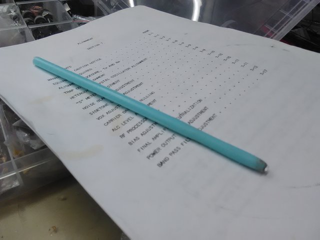
To do this a small vaned capacitor must be adjusted in the final compartment, accessible from the bottom. You need an insulated trimming tool, there is 600V DC here! But a plastic trimming tool is not strong enough to move the capacitor. I made a trimmer tool from a plastic coathanger and a small piece of thin aluminium. I cut off a long straight piece of coathanger and sanded down the top 5 or 6cm to a smaller rounded shape. Then I pushed a thin piece of aluminium into the end by heating the aluminium with the side of soldering iron.
9. Progressively lower power on bands above 80m, falling to about 35W on 10m
This is not yet solved. I have checked so many things and replaced several components in order to try and fix this problem. I put different valves in and neutralised but they performed even worse than the originals. They may or may not be junk. Plate and loading controls behave as expected. Can't get more than 40W out of the unit. The increased drive from changing the 2nd MIX DRIVER transistor brings maximum output to about 8.5 on the carrier dial rather than 10, so the limiting factor must be the PA and not gain through the TX chain.
Checked closely the bandswitch in the final PA area. Caps on the bandswitch did not seem cooked. Changed C104 (to 63pF, not 80pF). Checked R10 parasitic supressor, that was fine, assumed R11 and R9 underneath were ok as they were visually in great condition. Suspect valves, but in many boatanchor repair cases I have suspected valves and they've actually been fine, apart from a driver valve in a TS520.
Yes!!! I found the problem!! It was C11, a 200pF red lozenge type 1kV capacitor. It's hidden away in the bandswitch in the driver compartment, I had to snip it out and replace with a 330pF 1kV and 470pF 1kV in series (approx 193pF on the meter). This is a critical capacitor, the radio needs a realignment from scratch.
After some 'off-piste' realignment to get more power on 10m, I now have:
160m 110W
80m 150W
40m 140W
20m 120W
15m 100W
10m 50W <<< so somethings still wrong here. There appears to be some fade off of power starting at 15m. Undecided as to whether its driver valve, another bad component or alignment.
Yes!!! (again). 10m fixed! It is not possible to replace C11 with ceramic capacitors. C11 must be silvered mica. I have replaced it with a proper 200pF 1000V silvered mica capacitor. This resulted in more power on 10m - 60W - and disappearance of the power increase that happens the longer the transmitter was on.
Finally, readjusting T102 and T103 at 30Mhz got 120W out! Wow. Transmit output realignment was performed again and here is the final result:
160m 120W
80m 150W
40m 150W
20m 160W
15m 150W
10m 120W
( For comparison here is what I started with (probably the 3rd attempt at repair)
160m 2W
80m 150W
40m 80W
20m 10W
15m 5W
10m 3W )
10. Weak ALC action
There was at least a good ALC indication on 80m. Now however, there is only a whiff of ALC action on very strong voice peaks. This could be a new problem, or it could be related to the change of RF driver transistor mentioned earlier. To be investigated... This appears related to heating of R5 under transmit above 50W, which goes a little low in value, resulting in more gain and better ALC indication. I may have to order some high power rated resistors and a few nearby values.
Update: I replaced R5 with metal film power resistors 2 x 10k 3W in parallel, but the issue remained. The power increase was actually due to C11 capacitor substitution. This issue has gone with proper C11 200pF silvered mica fitted.
Testing with Steve MW0KST and his FT101, it turns out his Mic is high impedance 50kOhm and mine is low impedance 500 Ohm. This is the reason I seem to need a lot more Mic gain, the FT101 needs a high impedance mic.
Other things to be aware of:
When the plate trimmer board is loose and hanging down, don't let the 160m trimmer edge rest on the edge of the band switch wafer. It wrecks the side of the trimmer. Put something between them when poking around and measuring inside the compartment.
For (3, 4) you may have to adjust some inductors with wax in, depending on how bad the misalignment or twiddling is. Heat them up with a hot air station, I used 120 degrees with a smallish nozzle and directed the heat right into the core. Do not force the cores. You know you need those plastic trimmer tools.
600V DC. Lethal. Also 300V DC and 100V DC and -100V DC and 170V DC.
600V DC exposed in the transformer compartment. Very high voltages at several compartment feed through points.
Good luck!
- Details
- Written by Super User
- Category: Repairs
- Hits: 83371
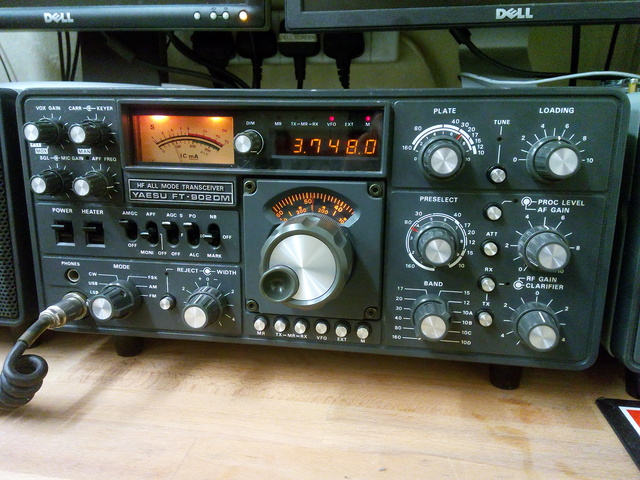
This radio has been waiting for some attention for a while, it's been tucked away for several years as I knew it had several problems with it. I swapped it for a working Yaesu FT757GX and power supply. What were you thinking you ask, swapping a working radio and matching PSU with a dead boatanchor? Well, an FT757GX is a rig. The FT-902DM is A RIG!
Problems:
1) CW keydown all the time from power on. This was a bad keyer chip a Curtis 8044 IC. These are unobtanium, so I just unplugged the board and put fitting a replacement homebrew keyer on the list. If you have a junker with the keyer board in, I need it!
2) Quite severe power fade under all modes. Full power for a few seconds then fading to half power. This was due to a bad capacitor in the PA, its on the final valve PCB. Remove valves, unscrew and desolder two wires. It's a red lozenge type 1kV 1000pF, the ones that seem to like dying in these old Yaesus. It's C01 on the diagram. After this I could get a full 100W on 80m.
3) Low power on bands 20m and above. Performed realignment as specified in the service manual. This got back everything except 12m and 10m
4) Replaced C70 200pF 1kV. Lozenge type. No change.
4) 11m CB conversion. It was modified for CB, so I only have 10A and 10B original crystals. I desoldered the CB crystals, luckily the sockets were still there, the wires were poked through the socket into the PCB. Folded over the crystal legs and fitted them back into the sockets, then fixed them with a small dab of glue. I need replacement crystals for 12m, 10C and 10D. 38.9875, 43,4875, 43.9875Mhz. Please help! Luckily, the digital counter was the version that did not need hacking to display the 11m frequencies correctly. However, the VCO unit has been readjusted for the changed bands 12m, 10A, 10B, 10C and 10D. I can't sort this out, or align at 30Mhz until crystals are obtained
5) Low power on 12m and 10m. Something has changed value. The preselectors in the transmit path still had the original glue on. I checked all over, checked the bandswitch, looked for mods, looked for burnt caps. Nothing stood out. Checked bandswitch contacts, wires. I measured the input to the final valves and it was low on 12m and 10m so it had to be something in the driver/trimmer/preselector sections. I really didn't want to but I had to know if the cans were adjusted right. So I marked the cores, removed the glue and tentatively adjusted. This got power back on 10m by adjusting T3 out a fair bit and then T2 out a little. Hmmm, performed realignment again. Got everything back apart from 20m, it needed an extra 22pF cap on the back of the large trimmer. I seem to have realigned around the problem, it remains to be seen if this is stable or will slowly drift off as whatever it is that is the root cause gets worse. T3 is around 4mm further up than the other cores.
6) PLATE tuning control pattern not quite as it should be. This is probably a cap or two that has changed value. To be investigated, but this isn't too bad or a showstopper. Could be related to (5).
Power out
160m 130W
80m-12m 100W
10m 95W with alc action!
- Details
- Written by Super User
- Category: Repairs
- Hits: 17244
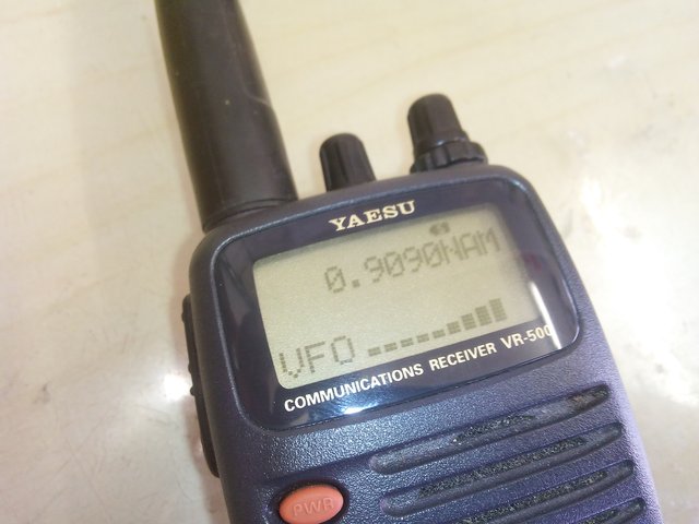
Nasty and horrid missing lines on your Yaesu VR500?
Don't panic, there is a fix. I wonder how many of these units have been junked due to this problem?
What you need:
Small screwdrivers.
Hammer.
SMT hot air station.
How to fix it:
- Remove batteries. Remove two case fixing screws inside the battery compartment
- Remove two case fixing screws at the top rear of the case
- Remove the Belt Clip and fixing screw
- Separate the case halves
- Remove the tuning knob by pulling
- Remove the SQL knob
- Remove the volume knob
- Remove the antenna if attached
- Remove the rubber washer on the antenna socket
- Remove the rubber washer on the volume control shaft
- There are three fixing nuts holding the controls and the antenna socket in place. Find a flat bladed screwdriver that fits nicely in the gaps on the fixing nuts. A bigger one for the antenna socket. Grab a small hammer.
- Sit down, clamp the radio between your legs. Put the screwdriver into the gap on the fixing nut, pointing along the direction of unscrewing, anticlockwise. Strike the screwdriver with the hammer several times, until the nut starts to move. Then tap gently to loosen it off. Then remove each nut by rotating it with the screwdriver. The antenna nut is done up quite tight, so try to get several good strikes in before you mangle the nut.
- They're all free? Yes! Remove the two black fixing screws holding the button and display PCB into the bottom of the front case.
- Remove the chassis from the front case
- Remove the side button cover and socket cover and seal
- Look at the display. It has a metal cover. At the top, with a small screwdriver, free the metal lugs by bending them away from the PCB and out. Free the metal lugs at the bottom by levering up the metal cover right next to them, they will bend and free with some force
- Carefully lift the glass screen up at the back, away from the plastic frame behind it. It's glued along the bottom, gently pull it until the glue separates. Don't yank it, you'll wreck it. If its glued really well, apply some IPA to soften it.
- When it's free, flip it forward
- Ease the plastic frame off the illumination LED at the side. Twist it up to free it at the bottom of the LED and then free it from the top.
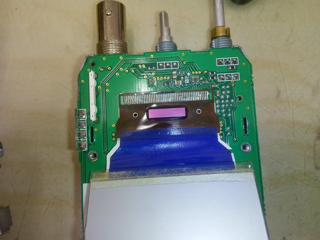
- The failure occurs between the contact of the brown plastic with the IC on it and the white plastic leading to the LCD. The top edge of the blue plastic covers the area of interest.
- Put a fine nozzle on your SMT heat gun. Set to 180 degrees and allow the temperature to settle. Move the nozzle quickly from side to side heating up the area of contact, right on the edge of the blue plastic. Don't hang in one place, it will melt the blue plastic! Quickly place the gun on the table and run your fingernail along the area of contact several times, with a reasonable pressure. Careful note: 180 degrees may be too much, there was a crackle from the blue plastic when it came up to temperature. Maybe try 140 to be safe, first.
- Fit some batteries into the rear of the case. Note how the power gets from the battery to the button contact PCB via two sprung contacts
- Fit the chassis into the rear of the case. The unit should switch on, flip the LCD forward. Check all display segments are present. If not, do the heating process above again. I had to do it twice.
- Remove the chassis from the case rear. Remove the batteries.
- Fit the clear plastic frame back into position, clipping the LCD back in. Locate the peg at the top in the PCB first. Then the bottom of the LED, then the peg at the right hand side
- Place the LCD screen back into the plastic frame, keeping the bottom flush with the edge of the frame.
- Straighten up the tabs on the metal frame. Fit it back into place. I bent the tabs at the top in a bit, didn't bother with the bottom ones.
- Put the plastic button covers, socket covers and seal back into place. The seal runs along the back of the unit.
- Place the chassis ino the plastic front cover, keeping the seal out of the way. Then push the seal into grooves along the sides and top of the front cover.
- Fit the two small black screws at the bottom of the button panel PCB.
- Fit the retaining nuts for the antenna socket and two controls. Place the small screwdriver into the cutouts on the nuts rotate them then push them tight
- Fit the rubber washers back into place for the antenna and the VOL control.
- Replace the SQL collar knob and the tuning knob. Replace the VOL knob
- Clip the rear of the case in at the bottom, then push the case halves back together. Fit the fine thread metal case screws at the top. Replace the belt clip and fixing screw. Fit the plastic self tapping thread case screws at the bottom, inside the battery compartment. Done!
- Details
- Written by Super User
- Category: Repairs
- Hits: 49887