[I haven't generated small images for this page, please be patient while it loads]
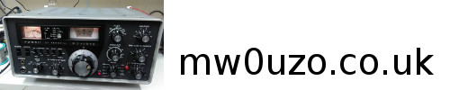
uBitx under construction. Extra signal processing arduino, touchscreen, 24V step up supply for the PA (40W out ssb 80m, 10W out ssb 10m), internal Raspberry Pi (waiting for Pi3 to arrive), space for internal LiPo battery approx 2500mAh at 14.8V. I should be able to squeeze SDR receiver in there, and the Pi will be able to control the transceiver, generate audio for datamodes etc. There will be USB and HDMI ports on the back and maybe the front too, for a wireless nano adapter and keyboard/mouse etc.
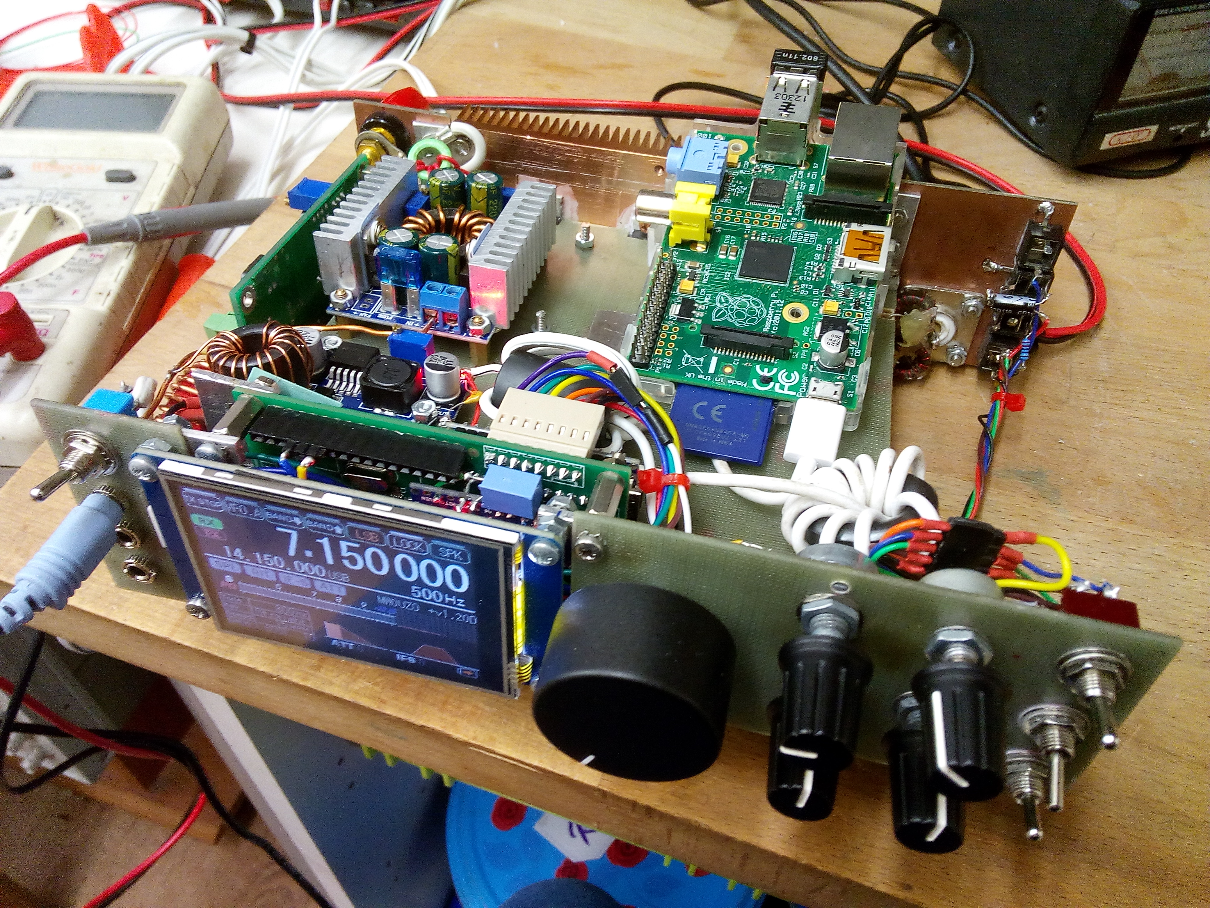
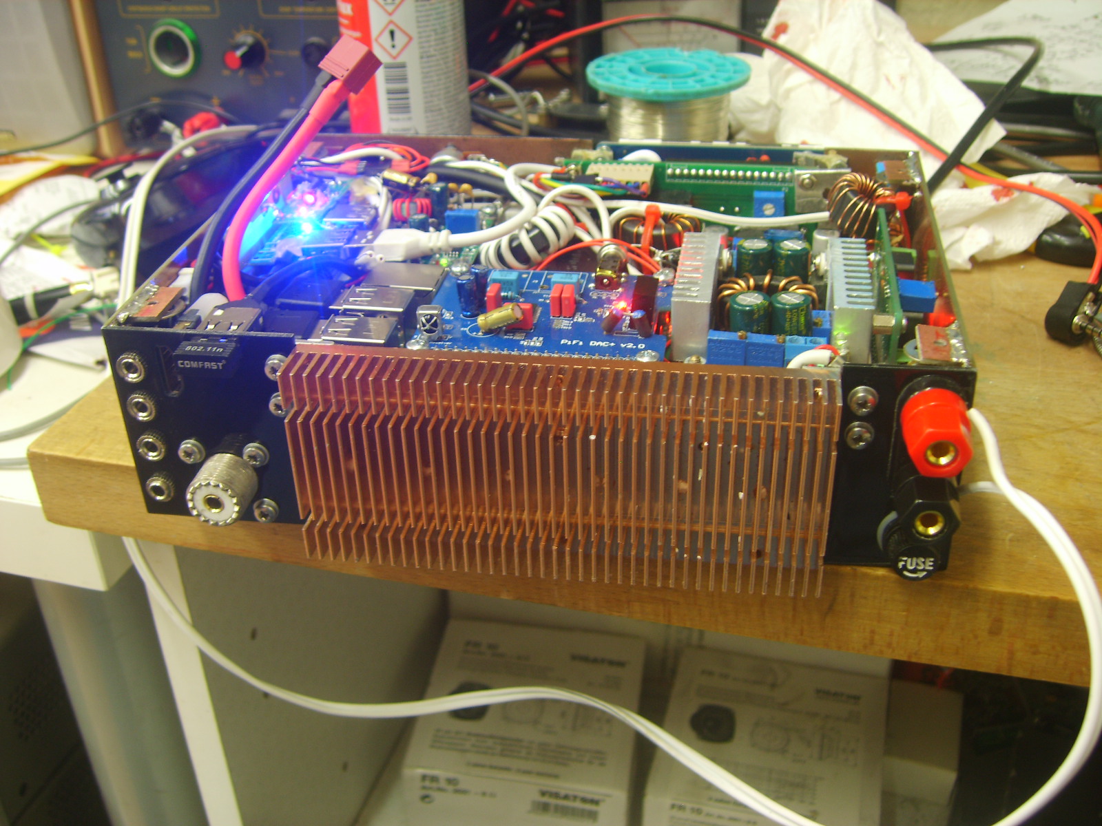
Power supply section of the uBitx. The vertical board is a 13.8V supply for the uBitx mainboard. This also powers the class D audio amplifier TDA8932 board for a power capability of around 7-10W. The audio board takes up to a 30V supply and delivers 30W, but that was excessive and I didn't want to accidentally blow up small speakers.
The square board with the heatsinks is the 24V supply for the PA, which can supply up to 8A, or 12A DC input. This also supplies the battery charge voltage.
The reason for including the 13.8V supply module was initally to provide charge voltage and a solid 15V for the uBITX. But the voltage required to charge the batteries to full (~17V) was too much for the uBITX. So that task moved over to the 24V supply. The main benefit of the additional switching converter is that the rig will operate at full power down to 10.5V.
The small one at the front is a 5V types for the display, backlighting etc. The arduinos run from a linear 5V regulated supply on the Raduino board, due to psu noise being too high for the audio processing on the signal board. These supplies are mounted on a centrepiece of copper clad board, which shields the RF receiver sections from the switching supplies and the Raspberry Pi. Initially, as expected, I experienced some interference from the switchers and computer, however I was able to reduce the interfering signals to surprisingly low levels by including large RF chokes at the power inputs of each module, preventing stray RF hash from going back into the main power supply line. Pretty much all noise has been eliminated from the supplies, but the charging module seems to operate in quite a rough mode and generates sweeping noise which I have yet to completely eliminate, despite adding inductors and caps over it to try to eliminate the problem. While I continue to work on solving the problem, I can use the switch on the front to take the battery out of charge mode, which eliminates the noise.
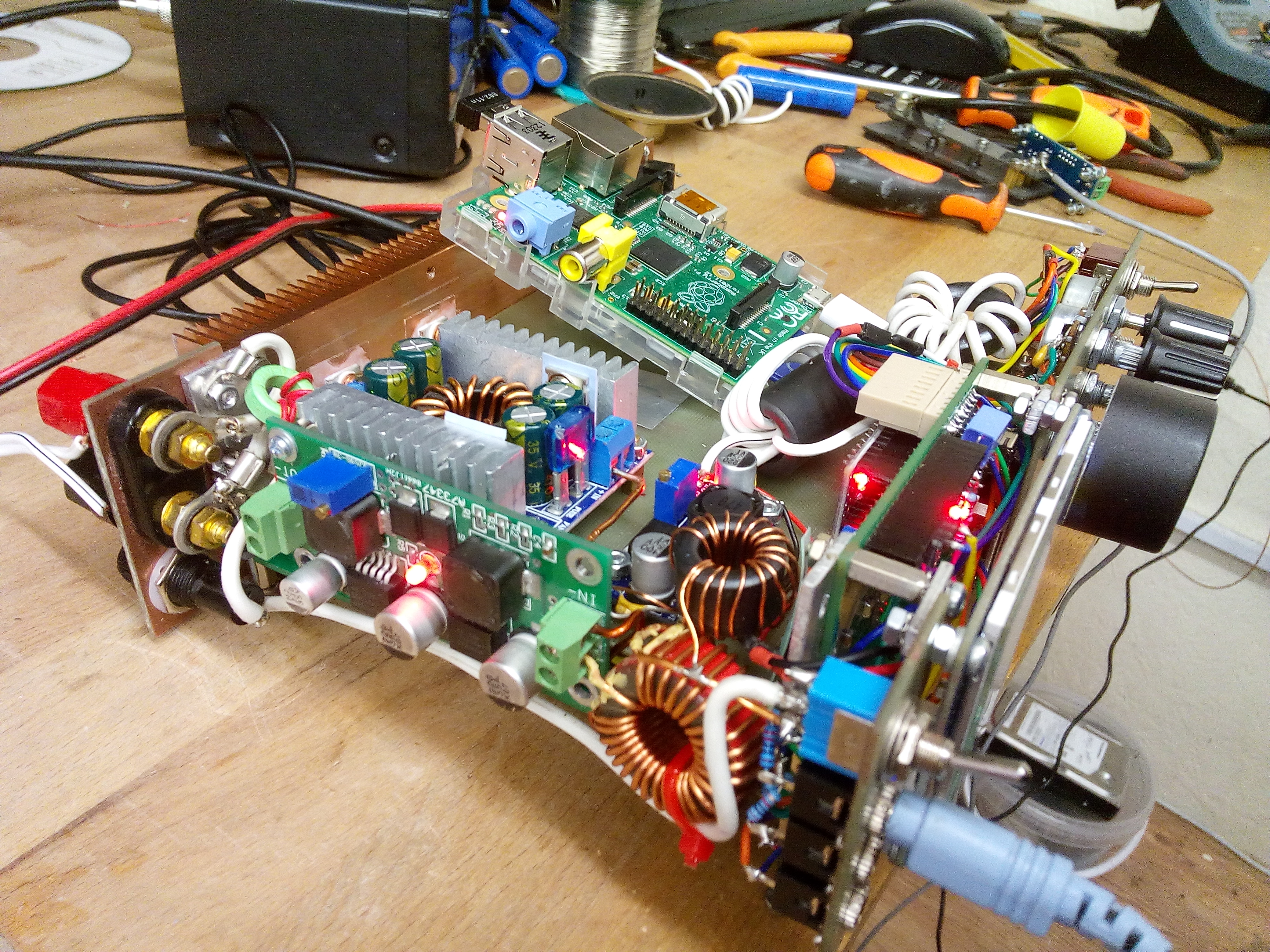
Some of the mods from left to right: SWR bridge, with forward and reverse voltage out trimpots. Anti-hiss LM386 mod. Variable filter bandwidth mod. It varies from about 1kHz wide to 3kHz wide. SWR protect and front panel drive control mod. RX to TX RF transient mod. PA mods: Upgraded inductors in PA+V line with thicker wire. Provided stouter PA +V feed with more wire. Audio mods: Replace 0.1uF caps in RX and TX audio amplifier with 22uF. Replace LM386 output capacitor with 330uF. Put 10uF across pins 1 and 8.
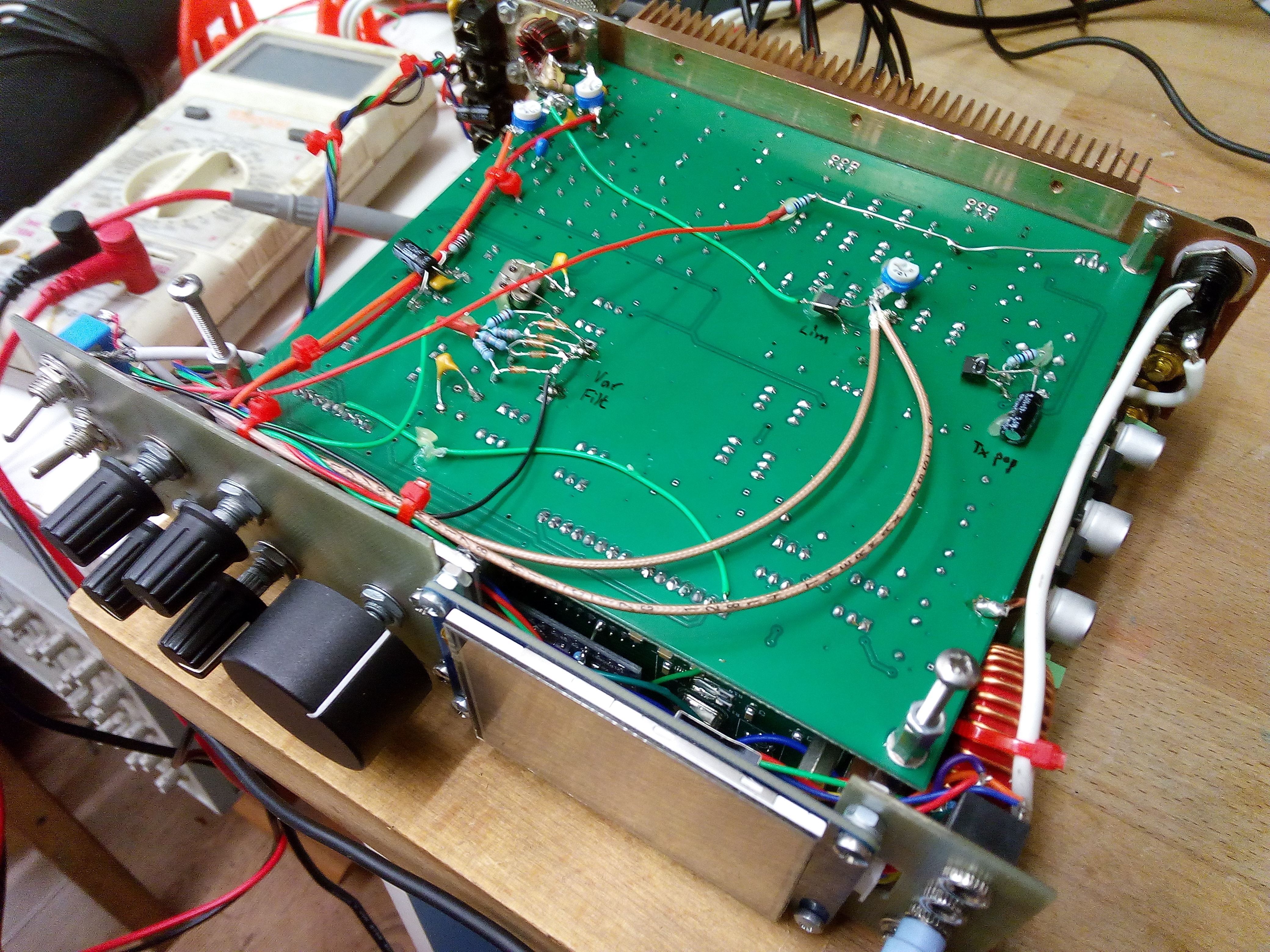
Stripping it down for spray painting... did not feel good taking it all apart again. You can see the uBIT board hiding underneath. Had I been thinking properly at the start of the project, I would have turned this board around and desoldered the sockets to put on the back instead. But then I would have to deal with turning the Raduino socket and board around to the right orientation. Ugh. Thankfully I can remove the uBitX board from the underside with minor amount of hassle, it does not require a complete strip down.

Test paint on smallest rear panel. Came out great.

It's back together! Didn't work properly at first due to short at the antenna input and rotated mic socket with contact shorted to case ground. Fitted 14.8V 2200mAh LiPo cell, battery protection board, charger, USB hub and audio device which was a super cheap £3 one from ebay. To save space I desoldered the plug and socket and mounted the audio board on the USB hub board. The USB connections are soldered on one end for both of the Arduinos, to save space. One of the cool development features with the internal RPi is that I can program both the Arduinos in place.

Rear of unit with WiFi nano adapter installed. Onboard Pi3 WiFi and Bluetooth disabled due to metal case. Space is an issue around the Rpi USB ports, requiring a slightly weird placement of the HDMI socket.
Case top and bottom painted.
Sides and backlight illumination fitted.

Marking up the front panel. This was a little annoying as I built the unit without a template, using what space I could to guide where controls could go. But luckily the manually marked locations were not wildly inaccurate.

The tuning knob is the recessed type, the shaft isn't long enough. I might have to make an adapter, use glue or 3d print something else... Borrowing a Dymo soon that prints white on black labels.

Onboard Pi3 running WSPR.

Labels ON! They were tricky to get straight, I adopted the method of using a length of waste label stuck to the corner or edge of the label to be fitted to place it, then pressing hard with finger when in the right place and pulling the waste length away.


The unit needs some proper feet. So, I found this M3 thumbwheel here https://www.thingiverse.com/thing:1564959 which also doubles as a foot when an M3 bolt is used as the stem. with a nut next to the screw head.

A picture of the unit at battle-station. We recently got a new TV so the old one has been put to good use!!
You may be looking at it and thinking - where's the cooling? Well I thought I'd try and get away with no fan, so it was completely silent. While it seemed to work fine on receive and transmit, internal temperatures were quite warm. Throw in the Pi crunching away hard and heat starts to build until eventually the CPU starts throttling. I fitted some copper braids that led off to the rear heatsink, which stopped the throttling. The reason for holding off fitting a fan was that I thought I would have to fit a 40mm fan in the case above the 5v power supply - the only place it would fit - and that it would be whiny and horrible. It took a week or two of knowing that it needs cooling and thinking about it before I realised that a solution exists that could use larger fans and no whine and no need to cut the case either.

Just by chance there is a gap of a few mm at the top of the rear heatsink. You can see the gap with the red leds shining through in one of the previous pictures. I could fit fans on the heatsink with a shroud that ensures air is drawn through the gap. Luckily I had two 60mm fans, that nearly filled the heatsink, so minimal shroud was needed, just top and bottom covers and a little bit of clear plastic to seal the sides. There is a path for air through the big hole for the jacks, along the rear of the screen, around the Raduino, across the large main circuit boards, through the gap and over the heatsink fins.

The extra depth from the fans is actually of no consequence, as the leads and connectors and wifi antenna are at least as deep as the heatsink/fan assembly. The fans run from the 5V supply when in RX and from around 9.5V on TX, using a 4.3v zener to drop some voltage from the 13.8V supply. There is plenty of cooling now, really that's got to be a good thing considering the extra juice the stock LPFs and RF output transformers have to deal with.
Ok.. some teething problems. I was getting RPiTX to work, into the dummy load and on 10m when a crack, sizzle and pop and a wisp of smoke came from the rig. This is something on the ubitx mainboard. I anticipate it is the RF output transformer. This sustained some damage to its windings from a mounting screw above it, the windings were crushed rather than the core moving out of the way. This was previously noticed and rectified after a crack and a sizzle occurred, but the damage was minor so the transformer was not replaced. To sort this problem for good I will flip out the mainboard and change to a 1:2 binocular core transformer. The heatsink will be removed, so while it's off I'll drill holes in it so air can be drawn through over both board levels easily. It's possible the original core of the transformer might be fractured, due to its small size and increase in PA voltage/power.

...yes it was the output transformer. It was replaced with a binocular core type. I tried a few different ratios - 3:5 gave a nice increase in power on the higher frequency bands 15W+ on 10m. However, there was some instability on 10m, so I fell back to 3:3, which was stable but 10w out only on 10m.

Holes in the heatsink allow air to be drawn over each level inside the rig.

It's busy in there now! The SDR receiver has been fitted and works well set to 45Mhz. Also RPiTX has been plumbed into the IF at 11.0556Mhz and transmits! I removed two 11.055Mhz crystals from one side of the IF filter to solve an annoying interference problem (reason not clear). I used them in series on the output of RPiTX and the 45MHz IF on the uBitX provides some extra filtering necessary to tidy up the transmit signal.
Some heatsinks have been fitted to the 5V power supply module as current draw is high when using the SDR. Also some heatsinks were fitted to the charge board. Fans are now disabled when in RX only, with the Pi off, as heat generation is minimal. For the SDR and RPiTX to work as a transceiver, i may need to install another USB audio card, or route Mic audio into the datamodes sound card under TX. QTCSDR, which allows use as a transceiver, seems to only like using the same sound card for audio input and output, so I think I'll have to install another. This is a problem, as all USB ports are now used, so another hub is necessary. I don't know if it will fit there, it doesn't look like it. We'll see.
Audio stream of RX, available when RPi switched on:
In use out in the field, I found I was missing two features that were necessary. The first was an internal switch to turn on and off the internal SWR protection. When enabled, it can make tuning on a sensitive Z match with indicator LED a little difficult, as the LED reduces brightness as the SWR increases. Also it can interact with an attached auto-tuner. So, if it annoys me I can quickly remove the bottom panel and switch it off. For shack and general use, I keep the protection on as tuning up is more refined and I can easily see where I'm at.
The second feature was a mic compressor. A SM2167 unit from ebay was fitted, set to 4:1 compression R1 = 51k with a 10k pot on the output set between 1/2 and 2/3rds way. The compressor is always on, as there is no switch available on the front panel. However, audio in at the back or from the Pi is injected after the compressor so it does not interact with datamodes etc.
Todo: SDR transceiver
Handy links and acknowledgements.
uBITX transciever board http://www.hfsignals.com/
KD8CEC firmware (brilliant work) http://www.hamskey.com/
Audio amp https://www.ebay.co.uk/itm/TDA8932-Amplifier-Board-Module-Digital-Mono-BTL-35W-Stereo-Parts-Accessories/113741023266?hash=item1a7b7e4822:g:lNIAAOSwPEdc0iol
PA step up module https://www.ebay.co.uk/itm/DC-DC-Step-Up-Power-Supply-Boost-Module-150W-8-16V-Charger-Converter-DIY-B28/323698560957?hash=item4b5df00fbd:m:mdylrjWhBl06SqnLElbo1-w