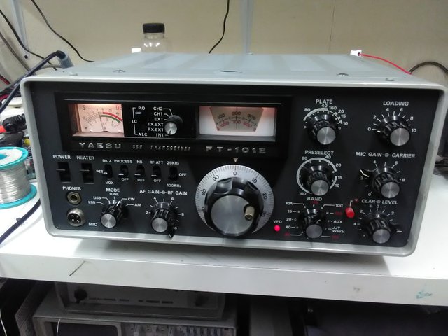
Radio with severe problems. This 'lovely' radio has haunted me for years!
1. Dead TX
R5 5.1k 3W in the driver valve compartment was cooked and open. Replaced. So was an electrolytic capacitor in there, underneath the long power resistor.. Replaced.
2. Very low power on 20m
20M plate trimmer bad and capacitor underneath it too. Replaced.
3. Misalignment
When following the alignment instructions for the preselector tuning coils, T101A would always end up 5mm up because the peak could not be found. The instructions say put the 10m trimmer TC15 to mid-capacitance position. I had to go for 1/3 capacitance position, then T101A would peak. The tuning slugs in the three inductor cans should not be in wildly different positions, mine are within 1mm of each other. Initial settings I found to be good for the slug position, when attempting realignment of the preselector coils from scratch were for the slug tops to be level with the white sleeve top at a preselector setting of 2 on the inner scale. I have read elsewhere that 4.1 is correct, but that would not allow me to tune preselect on the bottom edge of the band for 160m. At 2, it just fades off at 1.8Mhz and still allows tuning of the top end of 10m. So if the alignments are lost, preset the slugs to 2.
The S meter should be set to S9 for 50uV. The crystal calibrator is 50uV, so use that at 14.2Mhz to align the S meter. The service manual says to set it to S9+25dB, but this is too high in my opinion, especially for 80m.
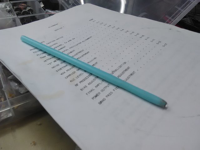
G3YRO's trimmers alignment procedure (thank you!):
The most important thing to remember on these rigs is that you shouldn't transmit full power carrier for more than a couple of seconds at a time, if you want the PA Valves to last. (do that and they will last 30+ years)
So when carrying out alignment on Transmit, always monitor the PA Current (Ic), and keep re-adjustinging the Carrier control to keep the current below 150mA. Also do each Transmit peak in short 2-3 second bursts.
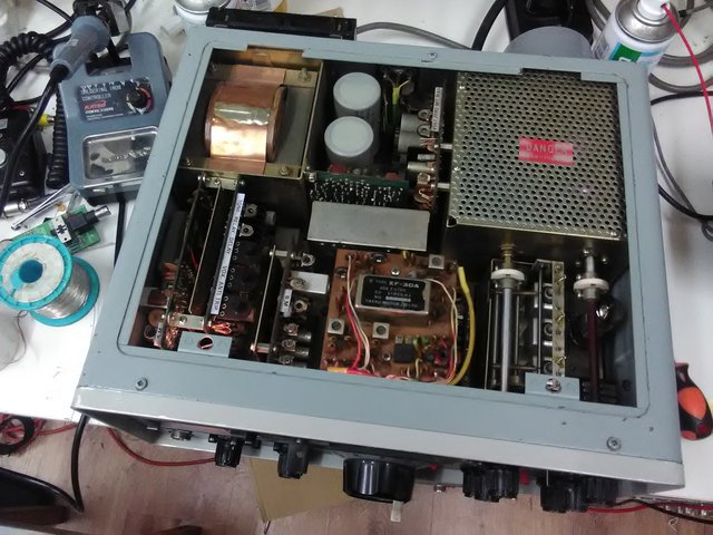
Stand the rig upright on its left hand side (on its feet), and remove the bottom plate. (no need to remove the Tx screening panel unnderneath).
Connect a Dummy Load
Leave the Mode switch in the Tune position.
Meter in the PA Current (Ic) position)
PA Load control at 0.
PA Tune control in the middle of the marked position for that band.
To gain access to SOME of the trimmers, you may need to just remove a couple of the case screws and pry up the case that overlaps the bottom, near the front of the rig. (with a flat screwdriver)
1. Starting on 80m, go to the middle of the band. Peak the Pre-selector on the Calibrator signal, and then leave it there.
2. Peak the Band Crystal trimmer for that band for max S Meter reading. Then go to Transmit (keeping the PA Current below 150mA) and peak that Crystal trimmer for max PA current.(this is because you can get a more accurate peak on Transmit)
3. On Receive, peak the RF Stage and Mixer Trimmers for maximum S Meter reading.
4. Go to Transmit, peak the Grid Tuning trimmer for maximum PA current. Then adjust the PA Tune control for a Dip (minimum PA Current). Then re-peak the Grid trimmer (it may have changed slightly).
5.Go to Transmit, peak the Mixer Trimmer for maximum PA Current.
6. Repeat all of the above for 40m, 20m, 15m and 160m bands.
7. Go to 10m, and peak EACH of the 4 band segment crystals on Receive, then Transmit. (as in Step 2 above) Do the same for the 11m Band Crystal.
8. There is NO Grid Tuning trimmer for 10m or 11m, so the procedure is slightly different.
9. Now go to the middle of 10M Band 2 (28.7MHz), on Receive, adjust the Pre-Selector for max S Meter Reading.
10. Go to Transmit and adjust the Preselector for Max PA Current.
11.Again on Transmit, adjust the 10m Mixer trimmer for max PA Current.
12. On Receive, adjust the RF Stage trimmer for 10m for max S Meter reading.
(note that 11m just uses the same settings as for 10m, so there's no Mixer or RF Trimmers)
4. Trap alignments
If your radio has been twiddled, do the trap alignments procedures as in the service manual. Ensure you keep an eye on the output power, as you have to go for spurious output supression *without* affecting output power. It's easy to completely get rid of the spur and forget about the power.
5. Intermittently low power
This was due to a crusty trimmer VR2 on the Modulator Unit PB1184A. Cleaned it.
6. No VOX operation
This one was particularly silly. VOX completely dead, no CW VOX no SSB VOX, no operation of relay when adjusting VR3 'RELAY'. I checked all over the board, changed electrolytic capacitors around the opamp IC, checked transistors and JFETs. Desoldered VR3 and cleaned it up, checked traces. Looked at how expensive a TA7024M was. With the unit back in I kept reading 0 volts on the trimmer when there should have been some voltage there. It turns out the label with 'TONE RELAY...' etc on it was pressed down a bit and it was touching the centre pin of the trimmer. The label is metal and of course grounded! Levering it back up straight solved the problem.
7. Low power on 160m workaround fix
On the RF Unit PB1181, the transmitter driver Q3 Trans 2nd Mix 2SC784R can be substituted with a S9018 chinese RF transistor. I subbed this to see if the original was OK and hadn't gone low gain. The S9018 offers more gain. Note the pinout is different so fit an insulator around the middle lead and twist the two leads. Check the datasheet for the S9018 and the pinout printed on the circuit board. I now get 100W. The increased gain of this device may have corrected for another problem not yet found, like a bad coupling capacitor somewhere. Readjust VR1 on the RF unit for minimum signal at 3.840kHz when TX on 3.8KHz, listening on a separate receiver.
8. Neutralisation
To do this a small vaned capacitor must be adjusted in the final compartment, accessible from the bottom. You need an insulated trimming tool, there is 600V DC here! But a plastic trimming tool is not strong enough to move the capacitor. I made a trimmer tool from a plastic coathanger and a small piece of thin aluminium. I cut off a long straight piece of coathanger and sanded down the top 5 or 6cm to a smaller rounded shape. Then I pushed a thin piece of aluminium into the end by heating the aluminium with the side of soldering iron.
9. Progressively lower power on bands above 80m, falling to about 35W on 10m
This is not yet solved. I have checked so many things and replaced several components in order to try and fix this problem. I put different valves in and neutralised but they performed even worse than the originals. They may or may not be junk. Plate and loading controls behave as expected. Can't get more than 40W out of the unit. The increased drive from changing the 2nd MIX DRIVER transistor brings maximum output to about 8.5 on the carrier dial rather than 10, so the limiting factor must be the PA and not gain through the TX chain.
Checked closely the bandswitch in the final PA area. Caps on the bandswitch did not seem cooked. Changed C104 (to 63pF, not 80pF). Checked R10 parasitic supressor, that was fine, assumed R11 and R9 underneath were ok as they were visually in great condition. Suspect valves, but in many boatanchor repair cases I have suspected valves and they've actually been fine, apart from a driver valve in a TS520.
Yes!!! I found the problem!! It was C11, a 200pF red lozenge type 1kV capacitor. It's hidden away in the bandswitch in the driver compartment, I had to snip it out and replace with a 330pF 1kV and 470pF 1kV in series (approx 193pF on the meter). This is a critical capacitor, the radio needs a realignment from scratch.
After some 'off-piste' realignment to get more power on 10m, I now have:
160m 110W
80m 150W
40m 140W
20m 120W
15m 100W
10m 50W <<< so somethings still wrong here. There appears to be some fade off of power starting at 15m. Undecided as to whether its driver valve, another bad component or alignment.
Yes!!! (again). 10m fixed! It is not possible to replace C11 with ceramic capacitors. C11 must be silvered mica. I have replaced it with a proper 200pF 1000V silvered mica capacitor. This resulted in more power on 10m - 60W - and disappearance of the power increase that happens the longer the transmitter was on.
Finally, readjusting T102 and T103 at 30Mhz got 120W out! Wow. Transmit output realignment was performed again and here is the final result:
160m 120W
80m 150W
40m 150W
20m 160W
15m 150W
10m 120W
( For comparison here is what I started with (probably the 3rd attempt at repair)
160m 2W
80m 150W
40m 80W
20m 10W
15m 5W
10m 3W )
10. Weak ALC action
There was at least a good ALC indication on 80m. Now however, there is only a whiff of ALC action on very strong voice peaks. This could be a new problem, or it could be related to the change of RF driver transistor mentioned earlier. To be investigated... This appears related to heating of R5 under transmit above 50W, which goes a little low in value, resulting in more gain and better ALC indication. I may have to order some high power rated resistors and a few nearby values.
Update: I replaced R5 with metal film power resistors 2 x 10k 3W in parallel, but the issue remained. The power increase was actually due to C11 capacitor substitution. This issue has gone with proper C11 200pF silvered mica fitted.
Testing with Steve MW0KST and his FT101, it turns out his Mic is high impedance 50kOhm and mine is low impedance 500 Ohm. This is the reason I seem to need a lot more Mic gain, the FT101 needs a high impedance mic.
Other things to be aware of:
When the plate trimmer board is loose and hanging down, don't let the 160m trimmer edge rest on the edge of the band switch wafer. It wrecks the side of the trimmer. Put something between them when poking around and measuring inside the compartment.
For (3, 4) you may have to adjust some inductors with wax in, depending on how bad the misalignment or twiddling is. Heat them up with a hot air station, I used 120 degrees with a smallish nozzle and directed the heat right into the core. Do not force the cores. You know you need those plastic trimmer tools.
600V DC. Lethal. Also 300V DC and 100V DC and -100V DC and 170V DC.
600V DC exposed in the transformer compartment. Very high voltages at several compartment feed through points.
Good luck!