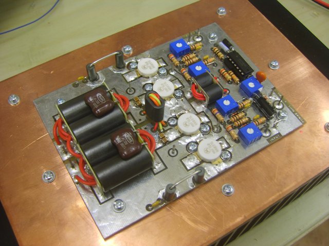
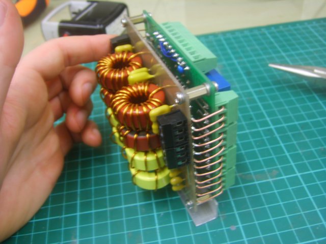
This is an amplifier based on the EB-104 Motorola Appplication Note by Helge Granburg. The amplifier PCB was purchased from eBay for approximately £10.
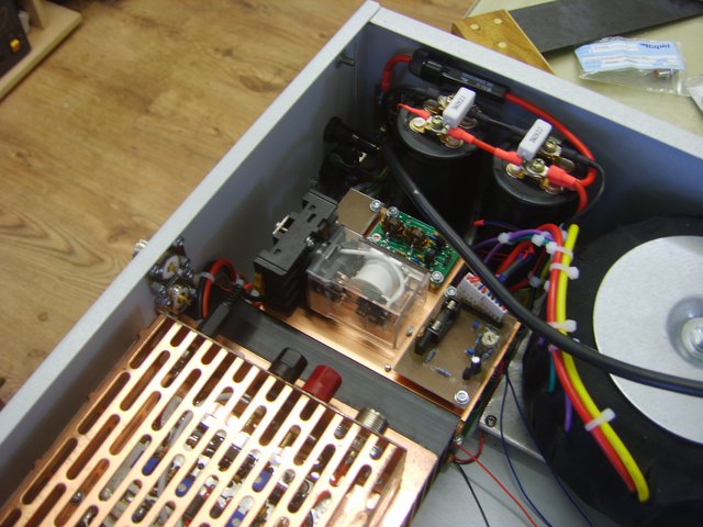
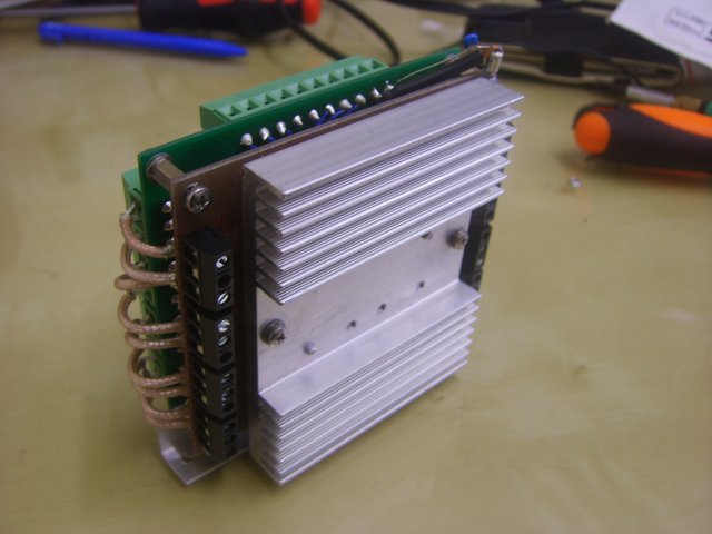
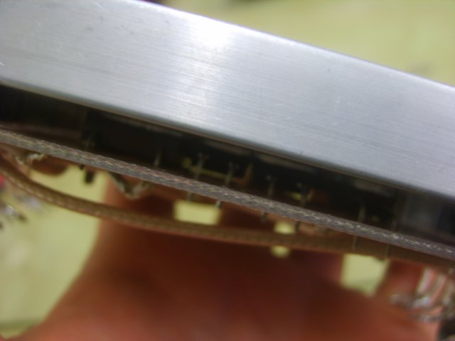
The MRF150 mosfets require a copper heatspeader to remove heat as quickly as possible from the device and transfer it to the aluminium heatsink efficiently. I used a 5mm thick copper plate, which was available at reasonable cost. Thicker plate is significantly expensive. The aluminium heatsink was tapped and the heatspreader drilled straight through. The copper was drilled slowly with engine oil used as cutting lubricant.
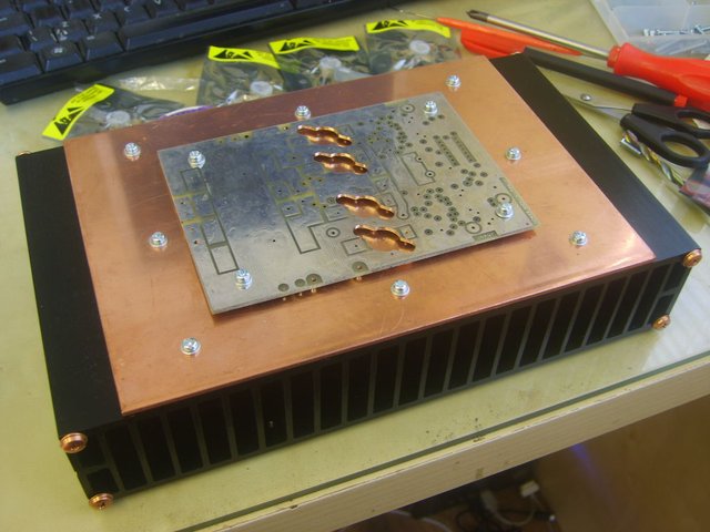
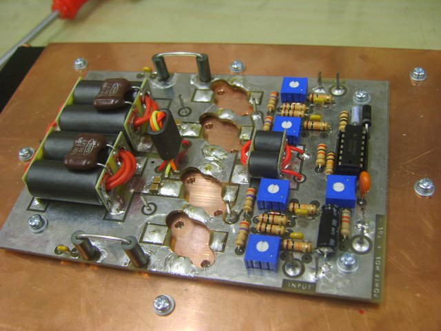
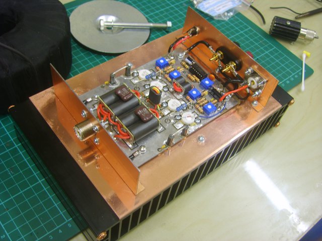
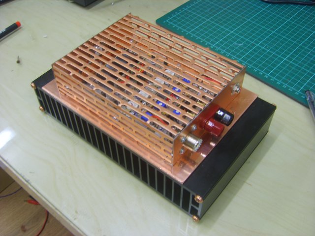
The mosfets used were cheaper, 'remanufactured' ones from China. The tabs on the transistors were shaped like bananas and did not sit nice and flat on the heatspreader. They had to be ground down to make a good contact. Upon discovering this, I was very worried about the mosfets, but decided to fit them anyway. The components were installed on the amplifier PCB. Some side plates made from the underside of a scrap amplifier were fitted and the amplifier wired up. A case cover was made from another part of the scrap amplifier that was vented. A 24V smpsu was used to begin testing the amplifier, with a low current fuse inline. The amplifier bias was set and the amp was carefully tested up to 100W of power without any smoke! Yes!
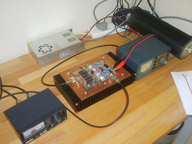
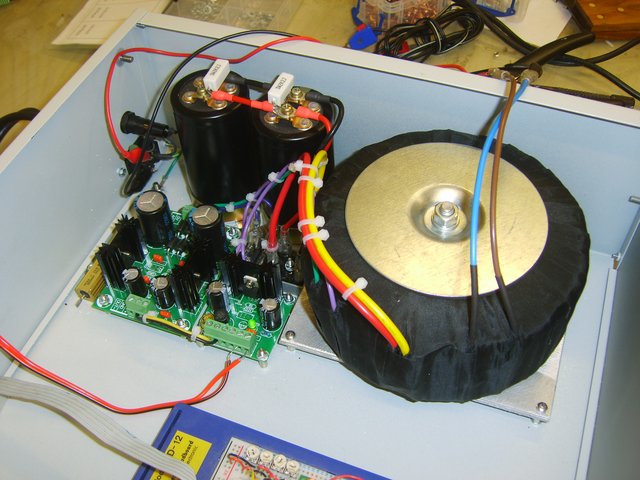
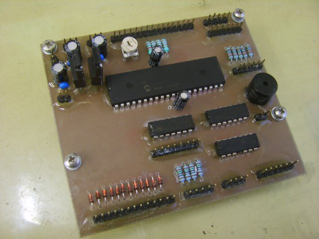
The next part of the amplifer to build was the 50V power supply. A custom transformer was ordered providing a single heavy duty 30A 40V AC 50% duty cycle winding, with an ancillary 3A winding 14-0-14V for the +12V,+5V and -12V supplies. A linear supply was chosen to eliminate the chances of RFI from an unknown SMPSU. The regulated ancillary supplies were ready made modules obtained from eBay. To test them, the breadboard controller prototype was connected. The controller uses a 16F887 PIC microcontroller, with some additional shift registers for plenty of outputs. The code from the beacon project was tidied up and moved over to the better PIC to provide a good base for developing the new code.
The mains switch was fitted and the amplifier module wired up for the first 50V test... and thankfully it didn't go BANG. After rechecking the bias, I was able to get several hundred watts from it, and avoided (as much as I could ha) testing it without any form of over-current or SWR protection. I have to admit to testing it without the required protection plenty of times and also forgetting to connect a dummy load once. Luck was on my side, no mosfet death. Others have not been so lucky.
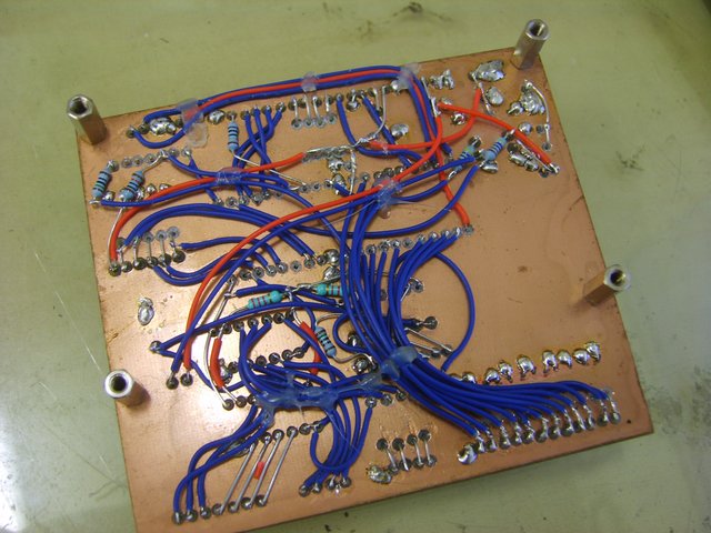
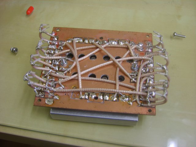
Next - make the controller module. This was made on copper clad, with the wiring on the back like the beacon. The LCD display is also bolted to it, and the whole module fixes to the front panel with four screws. Several months were spent developing the code in ASM, it was a significant project.
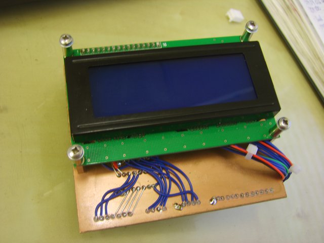
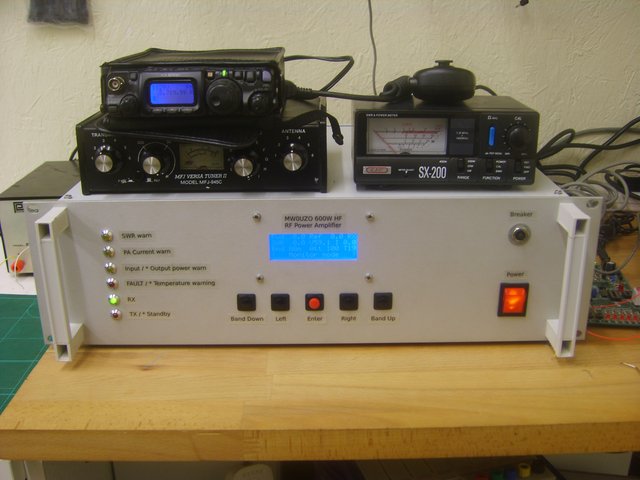
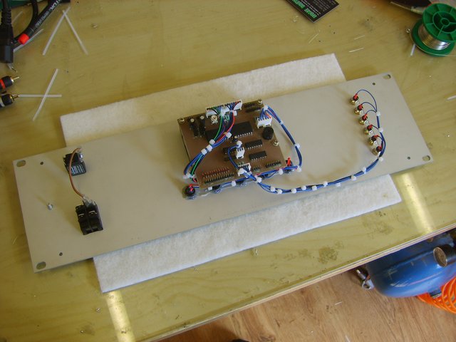
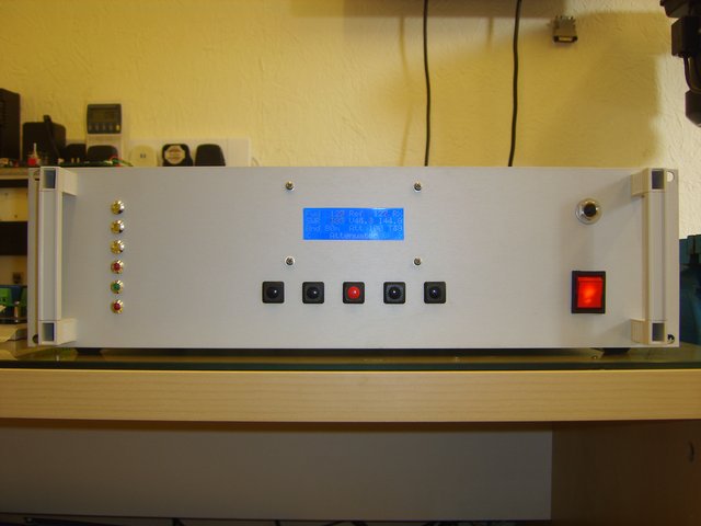
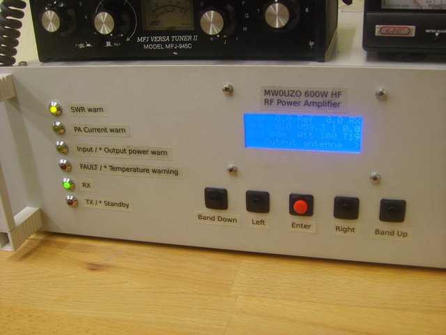
The completed module was fixed to the front panel, along with the status LEDs and control switches.
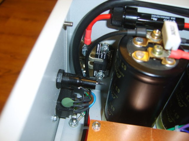
An ACS758 current sense module was fitted to monitor the transmitter current. Initially I was going to use a low value resistor, but once I had discovered this module then it saved a lot of time. An initial attempt at soft start using some surge suppressors was also installed. This failed, as they could not handle the inrush from the massive transformer. Larger suppressors taken from an old audio amplifier were fitted and a relay to bridge them out a few seconds after switch on.
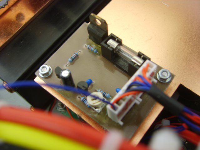
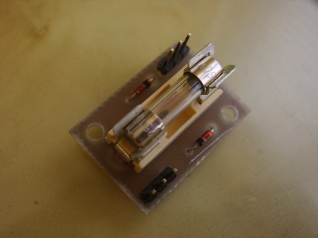
Most of the amplifier has digital protection. However, for the current, instantaneous protection is required for overcurrent peaks. This was accomplished with an analogue fast protection board, that cuts off the amplifier bias if the limit is exceeded. This board also has a potential divider for monitoring the power supply voltage. The input protection failsafe is in case the digital protection fails and to suppress instantaneous spikes. It is a 500mA fuse, with back to back 31V zeners, to clamp the voltage at 31.7V and draw increasing current during overload, blowing the fuse. These boards are mounted on a plate which fixes on top of the PSU regulator modules. The large RX/TX relay was initially chosen due to its large contacts for potentially switching 100W of live input RF in RF sense mode. However the loops of wire connecting to the contacts within resulted in bad SWR at 28Mhz, so it was replaced with a smaller relay.
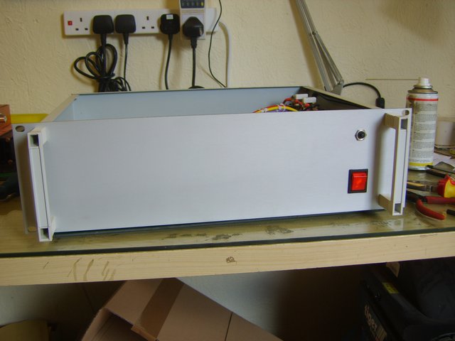
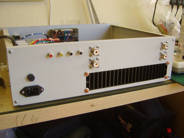
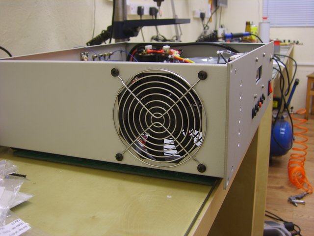
Then the rear panel was cut to fit the RF sockets, control phonos and exhaust vent. There are two inputs for connecting two transceivers and two outputs for connecting antenna. The phonos are PTT, TX inhibit, ALC and remote standby/bypass. The remote standby/bypass switch is for when the amplifier is fitted into a rack that may not be immediately accessible to control the amplifier. The 120mm fan was fitted to the side of the case.
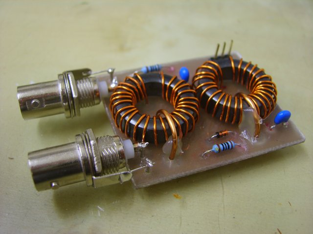
To protect the amplifer there are four SWR bridges. One 600W version at the output of the amplifier module, one 600W version after the LPFs, a 100W version in the input path and a 10W version at the input of the amplifier module. The 600W versions have 25 turns on the transformers, and the 100W version has 20 turns. The 10W SWR bridge is a modified QRP kit from kitsandparts.
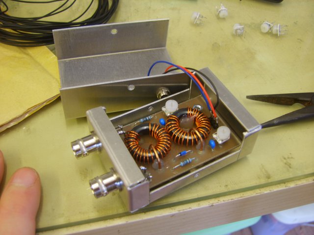
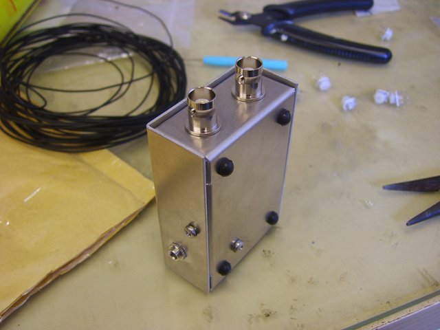
The amplifier has three internal dummy loads. There are two 100W versions for each input to the amplifier and a huge 500W continuous version for the output of the amplifier. This allows testing of connected transceivers and the amplifier by using the menu.
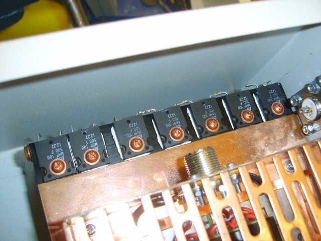
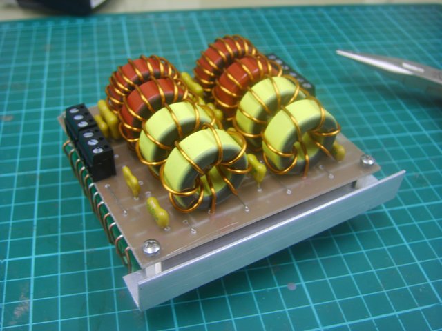
The LPF modules are made from relay boards, with copper clad boards attached. The copper was cut with a dremel tool and cutting disk to form the tracks. The relays are connected to the lpfs by pieces of coax and wire. Initially, all wire connections were used, but there were SWR problems. Some connections were changed to coax, solving the problems.
So that the amplifier can be driven by a range of different transceivers, three fixed attenuators were made, capable of dissipating 100W,50W and 25W. There is a straight through option for 10W. The attenuators are made from TO220 and TO247 style thick film resistors. The rear of the attenuator board is connected up with coax, its a bit messy but it works.
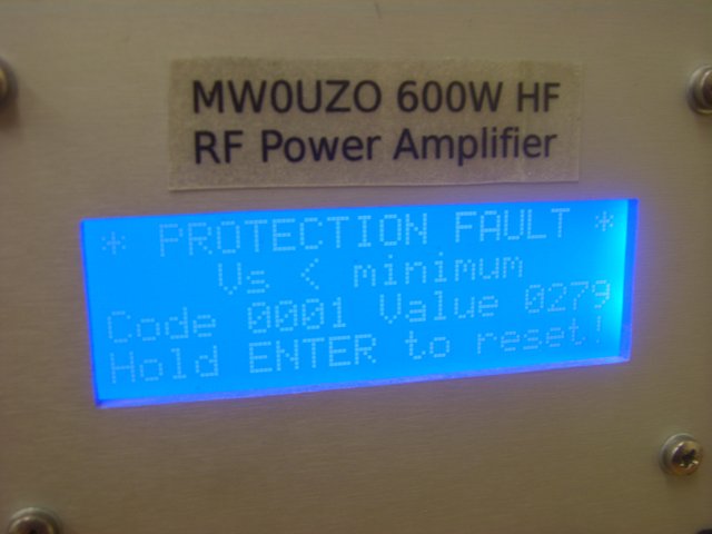
If the amplifier detects a fault, then it goes into a safe state, activates a loud buzzer and displays each of the faults detected, with ADC values and error codes so that the fault can be analysed. There are warning lamps that stay lit if warning thresholds are exceeded. The amplifier has many monitor pages, for checking and reading off measurements while operating. The power measurements can be set for instantaneous reading, or peak reading.
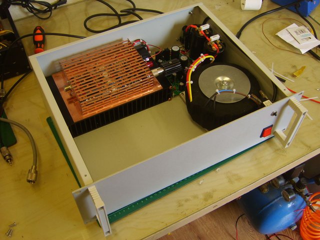
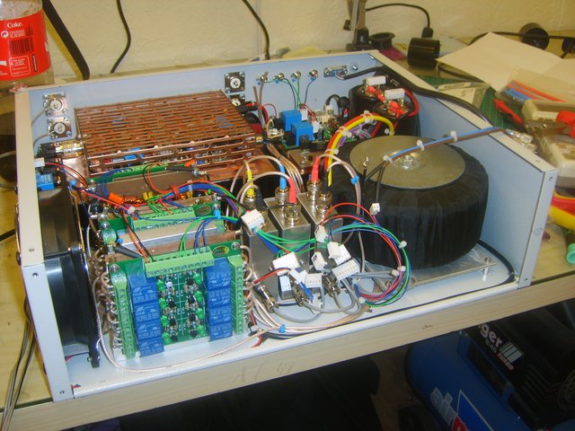
A closeup of the attenuators, LPFs, SWR bridges and control boards. View of the amplifier with the front removed.
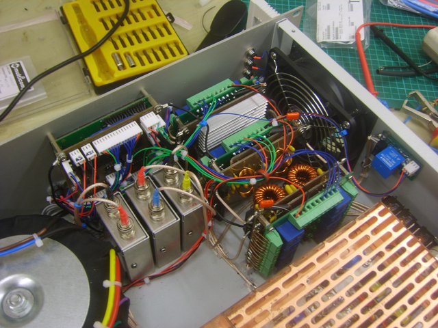
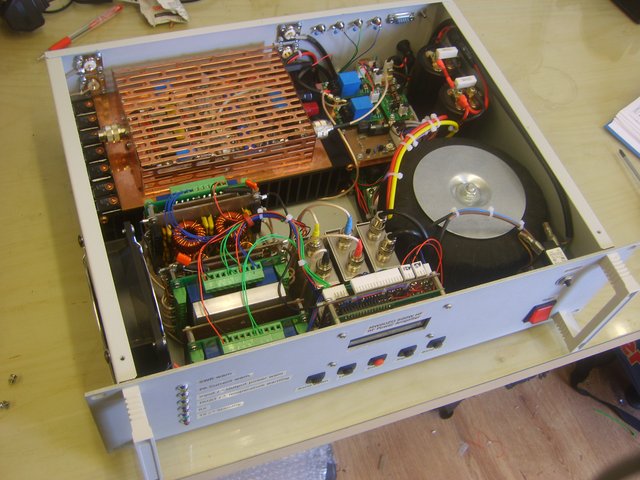
Inside view of the finished amplifier. There's still some room left. Enough for a small auto-ATU?
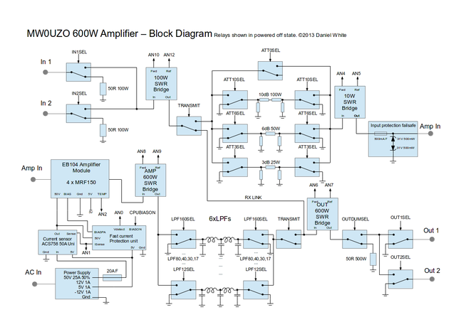
Block diagram:
And thats it. Approximately 1 year of work to complete, and it works very well, runs cool, clean and has plenty of headroom. The comprehensive protection and monitoring picks up all sort of faults and has saved me from operating mistakes and undetected antenna/feedline problems many times. I am quite happy to completely disconnect the antenna and give the amp a blast and know that it will work fine after reconnecting the antenna.
Work left to do and problems to fix:
- Implement auto detect of band from input frequency. The code for counting the pulses work and the input circuitry on breadboard works. The amplifier controller need to be dismantled to fit the circuit and the code written for deciding which band is needed.
- Low level RFI pickup from controller due to lack of screening and proximity to attenuator module. The level is in most cases is lower than the noise floor, so this hasn't really bothered me. I will get some copper tape and form a shroud for the controller and/or the relay side of the attenuator module.
Notes for other builders:
The bias thermistor is best placed onto the heatspreader, not on top of the transistor. Include a 4.7k resistor in series with the thermistor to make the bias current level with temperature. Check the bias to ensure it is level or reduces slightly with increased temperature. Fitting the thermistor on top of the transistor results in a too great bias reduction too quickly, which affects distortion and output power. It is normal for bias to become elevated as the transistor heats above the temperature of the heatspreader. Not including extra resistance results in too great a bias reduction with temperature, with loss of power as the amplifier is used.
- Modifications for the EB104 board. The small capacitors across the power supply need to be changed for larger, higher voltage types. Good quality RG-58 coax braid can be soldered across the mosfets to improve the RF ground. Add a further thick GND wire leading to the central part of the PCB. I found I did not need multiturn bias pots. I set the reference pot to 5.5V. The bias must be set with the thermistor lifted from the heatspreader, otherwise the bias settings will be wonky because of the slight increase in temperature of the heatspeader as you work.
- The EB104 has increased distortion on 40m. This gave me an increased SWR reading on 40m at the amplifier output due to reflection from the 40m LPF. My minimum SWR was 1.7. For ages I tried to fix the problem. Suddenly I had a brainwave, I calculated the SWR from the distortion figure at 7Mhz - 1.7:1.
- Choose a good way for mounting your LPFs on aluminium plates or inside a box, and choose a different method of construction. I had several problems from RF getting into the relay control transistors and a poor RF ground causing the relay ON signals to disappear. Not good at high power. Luckily I was able to sort out the problems with plenty of bypass capacitors, resistor changes on the relay board and a screening plate made from copper clad fitted between the lpf and relay board. All these annoying problems could have been avoided with better planning of the LPF modules.